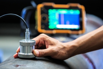
What are optical CMMs?
Traditionally, CMMs (coordinate measurement machines) are large, static, and contact-based. But optical CMMs like 3D scanners are changing the game, allowing for rapid, zero-contact 3D measurement with greater versatility. In our article, we break down the differences between the technologies, explain how they work, and explore the very latest inspection solutions.
What is an optical CMM?
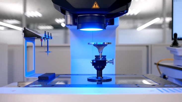
A Zeiss O-Detect optical measurement machine analyzing a medical component. Photo courtesy of Carl Zeiss AG
It’s probably easiest to begin with a definition of a traditional CMM. Essentially, CMMs are machines that measure with precision using physical probing. Built around XYZ linear axes, such devices record the position of geometric features in a 3D space. The technology is particularly adept at high-accuracy 3D measurement and detecting obscure surface details.
However, traditional CMMs also tend to be quite large and pricey to operate. When working with fragile products, probing can even cause damage, limiting their application in certain use cases.
Optical CMMs, on the other hand, are purpose-built for non-contact 3D measurement. These capture object geometry using technologies like cameras, lasers, and structured light – there are numerous types of optical CMM, but all have metrology applications.
The evolution of CMM technology
Early CMMs were manually operated, relying upon dial indicators and hard probes. It was only when analogue sensors and servo-driven axes were introduced in the 1960s that computer control and 3D measurement became possible. Since then, analogue systems have been replaced by digital encoders, further improving accuracy and repeatability.
Key point
Traditional CMMs operate using physical probing. Many optical CMMs offer a contact-free, versatile alternative.
Modern CMMs now offer multi-sensor probing (touch-trigger, scanning, optical, and laser), and operate using metrology software that allows for greater automation than before. Recent advances have also broadened the pool of technologies available to engineers. Optical CMMs have brought greater speed and versatility. Elsewhere, AI integration, cloud computing, and the wider field of digital twin diagnostics are allowing for integrated Industry 4.0 workflows.
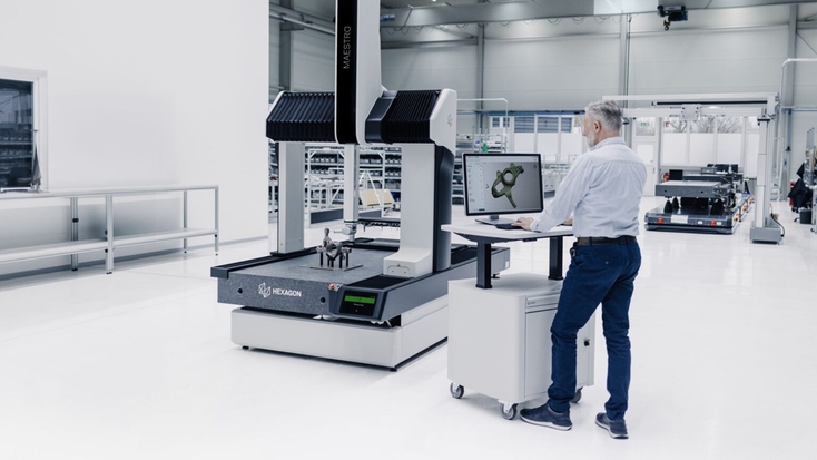
A multi-sensor CMM, equipped with touch-trigger probes and a non-contact laser scanner. Photo courtesy of Hexagon AB
How do optical CMMs work?
Depending on the type of CMM, your workflow will be slightly different. Most lab-based optical CMMs require users to place parts on a platform. Capture technologies like white-light, high-resolution CCD/CMOS cameras, and laser triangulation sensors are then used to detect object surfaces without requiring physical contact. Other handheld devices are similarly contact-free, but allow users to navigate manually for greater flexibility.
Once captured, data can be analyzed via CAD model comparison, or simply measuring the distances and angles between features to ensure results are accurate and within tolerances.
Generally, optical CMMs are large, static machines. But many users are now starting to adopt another kind of CMM: 3D scanners. These boast enhanced maneuverability and speed, but we’ll get into technology comparisons shortly. For now, it’s worth noting that optical CMMs can take on many forms, with some prioritizing peak accuracy and others designed for versatility.
Optical CMMs rely on one (or more) of these technologies:
Vision/camera sensors: In these setups, a camera captures a part illuminated by controlled lighting. Image processing algorithms then detect features like edges, holes, and patterns. The main drawback is that they only measure in 2D, unless combined with Z-focusing (focus variation).
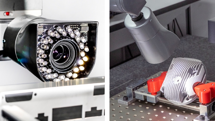
An HP C vision sensor in action. Photos courtesy of Hexagon AB
Time-of-flight/phase-shift: Machines built around these technologies also rely on lasers. However, they calculate distance differently: either by measuring how long it takes for lasers to return, or laser phase difference. They tend to be better from a distance and less precise over short range. Overall, they allow for direct measurement while remaining contact-free.
White/chromatic light: This approach revolves around chromatic aberration – where different wavelengths of light are fired at an object from varying distances. White light is emitted through a chromatic lens, with each wavelength that comes into focus being detected by a spectrometer. Using the technology, it’s possible to work out exact heights and achieve high axial resolution.
Laser triangulation: Essentially, this method involves forming a triangle between a laser source, part surface, and detector. Once the laser reflects back off the object, triangulation is used to work out the distance between the emitter and the surface. This method is great for capturing 3D profiles and items with rough surfaces.
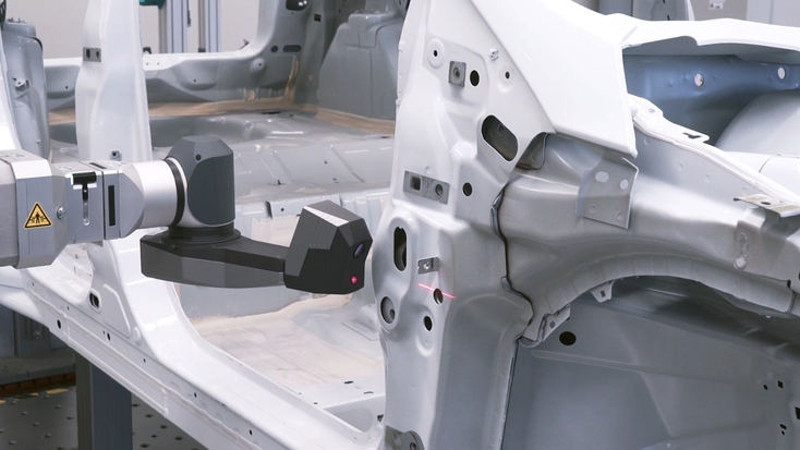
A car body being inspected with a laser triangulation sensor. Photo courtesy of Carl Zeiss AG
Structured light: Projecting patterns like stripes and grids onto a part and measuring how they deform due to surface geometry is great for digitizing and analyzing large areas, as well as capturing organic shapes. The technology is often used for 3D scanning, but also applied elsewhere.
Confocal sensors: Lastly, some machines rely on confocal optics. These focus light into a tiny spot and measure the intensity of reflected beams to identify a specific focal plane. In practice, this means only the sharpest reflections are captured, allowing for nanometer-scale resolution.
Different types of optical CMMs
Tactile CMMs – Ideal for inspection cases where tolerance for error is low, these machines rely on physical probe measurement. This category includes bridge, cantilever, and gantry CMMs.
Hybrid optical CMMs – These tend to vary by vision technology, e.g. video measuring systems, confocal microscopy CMMs, and white-light interferometers. It’s also worth noting that hybrid optical CMMs combine tactile and vision-based approaches, albeit in static machinery.
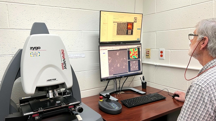
An engineer at the University of Wisconsin – Madison using a Zygo New View 9000, a white-light & phase-shift interferometer. Photo courtesy of the Wisconsin Centers for Nanoscale Technology
3D scanners – Technically also optical CMMs, 3D scanners tend to rely on laser or structured-light data capture. Systems can either be fixed to a tripod or robotic arm – or operated by an engineer and maneuvered around a target object.
Artec 3D scanners as optical CMMs
Artec Micro II
Artec 3D scanners now boast such high-accuracy 3D measurement capabilities, they can be considered optical CMMs in their own right. Artec Micro II captures anything small enough to fit into your hand with up to 5-micron accuracy and 2-micron repeatability. Better yet, thanks to its integration with Autopilot in Artec Studio, data captured with the device can be processed automatically.
Inside the 3D data capture and processing software, it’s now possible to initiate scanning and 3D model creation at the click of a button. Once activated, the Micro II rotates objects on its axes, capturing them as it goes. Mesh data can then be dropped off at a designated folder, where it can be auto-transferred for analysis in an end-to-end inspection workflow.
Artec Metrology Kit
Those seeking a dedicated metrology solution should check out the Metrology Kit. This full 3D optical coordinate measuring system delivers an incredible 2-micron accuracy for reverse engineering, inspection, and 3D measurement with pinpoint precision.
Applications include analyzing deformation in huge builds like turbine blades, automotive quality control, and R&D at scale. Operating with six degrees of freedom and DAkkS certification, the Metrology Kit is a highly reliable solution for addressing the most accuracy-critical use cases.
Artec Point
Moving on to portable CMMs, Artec’s first laser scanner, Artec Point, offers high tracking stability, while being agile and accurate enough to warrant serious consideration as a metrology tool. Tested against VDI/VDE standards under ISO-certified lab conditions, the device meets all the required qualifications you’d expect of an industrial data capture solution.
Capable of measuring objects of different shapes and sizes with up to 20-micron accuracy and resolution, Artec Point features HD cameras and an innovative ‘angled’ design. This allows it to pick up difficult-to-capture geometries and peer into areas like deep holes. With three scanning modes for different types of surfaces, users can switch between a grid for large objects, parallel lasers for intricate surfaces, or a single laser for seeing into holes and crevices.
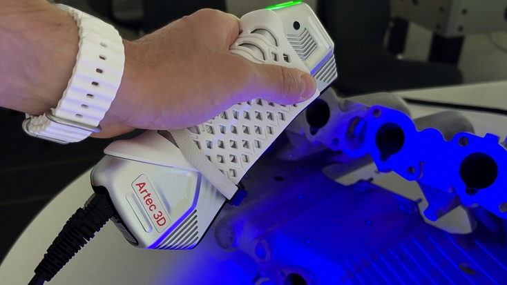
An automotive part being 3D scanned with Artec Point.
Unlike other Artec 3D scanners, Artec Point does require targets. But industrial manufacturers seeking metrology-grade handhelds see a lot of value in solutions with high accuracy and portability – and Point ticks a lot of boxes in this respect.
Artec Leo
When it comes to untethered 3D measurement, nothing on the market comes close to Artec Leo. If Point is versatile, Leo offers practically unlimited capture freedom. The all-in-one portable CMM is completely wireless, captures at a pace of up to 35 million pts/s, and comes with a built-in screen that allows users to ensure full capture. Its 0.1 mm accuracy may be a turn-off for those working in demanding use cases, but it’s still sufficiently accurate for most others.
For example, in applications like oil and gas pipeline repair, Leo allows users to seamlessly scan hot, difficult-to-access areas with sufficient accuracy for repair clamp customization. In cases where greater reach is required, Ray II can also be used to capture facilities or infrastructure, with Leo picking up machinery and fine details within – where they really matter.
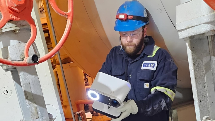
Pipework at an oil refinery being captured with Artec Leo. Photo courtesy of Team, Inc.
Key point
With complete wireless functionality, a built-in display, and target-free operation, Artec Leo is a uniquely portable CMM.
Artec Ray II
LiDAR isn’t often viewed as a metrology solution, but scanners like Artec Ray II do allow for inspection on a grander scale. Many traditional CMMs are limited by object size. But Ray II can be carried to site and set up to scan entire buildings and infrastructure from 130 meters away with high accuracy. This makes it ideal for monitoring bridges or creating factory digital twins.
Thanks to its broad reach, Ray II can also access applications beyond regular CMMs, whether it be capturing forensic crime scenes, lengthy railway tracks, or entire heritage sites.
Key point
3D scanners come in all shapes & sizes – so you can choose a metrology solution that meets your exact industry needs.
Key features
Accuracy & precision: Optical CMMs may not be able to hit the peak accuracy levels of tactile alternatives. But they can capture with sub-millimeter accuracy (sometimes even reaching a few microns), which is more than sufficient for the majority of 3D measurement applications.
In metrology, high precision effectively means being able to measure with high repeatability. This makes precision critical to achieving trustworthy results in the manufacturing space, where deviations can lead to product failure. Optical CMMs like Micro II offer outstanding repeatability, so users know they can measure while adhering to strict specifications and standards.

The compact, 0.005mm-accurate Micro II 3D scanner offers a great alternative to traditional optical CMMs when you need to inspect small parts.
Capture speed: Compared to probe measurement, optical CMMs are often much faster. The structured-light-powered Artec Leo, for instance, captures small objects in minutes. Obviously, it depends on the technology you adopt. But generally, non-contact CMMs (whether they be laser or optical) will deliver results more quickly than traditional tactile data collection allows.
Versatility: Traditionally, CMMs are fixed in place to prevent external vibrations from interfering with measurement, limiting them to in-situ data capture. By contrast, portable CMMs can be mounted to robotic arms or deployed independently. In theory, the latter unlocks limitless possibilities – manufacturers can analyze product quality whenever, wherever they need to.
Data processing: Probe-mounted CMMs turn captured points into coordinate systems, which, in turn, can be used to reconstruct features. Instead, optical CMMs like 3D scanners turn point clouds into meshes. Dedicated CMM software is often better equipped for GD&T, but programs like Geomagic Control X are helping 3D scanning catch up fast.
Integration: Optical, portable CMMs are less restrictive than traditional CMMs, allowing for both hardware integration with robotic arms and the utilization of third-party analysis software.
Key point
Captured 3D scan data can be analyzed in popular software like Geomagic Control X & PolyWorks.
Applications
Manufacturing & quality control
Optical CMMs can be integrated directly into the production workflow for measuring parts in batches, or used at-line for checks in between runs. The technology is also perfect for ensuring that parts sourced from elsewhere meet desired standards. Ausco Products is a great example: the off-road brake manufacturer inspects outsourced castings using Artec 3D scanning. As well as tolerance testing, the technology allows the company to check if brakes will fit into tight areas like wheel wells, in a way that accelerates product customization.
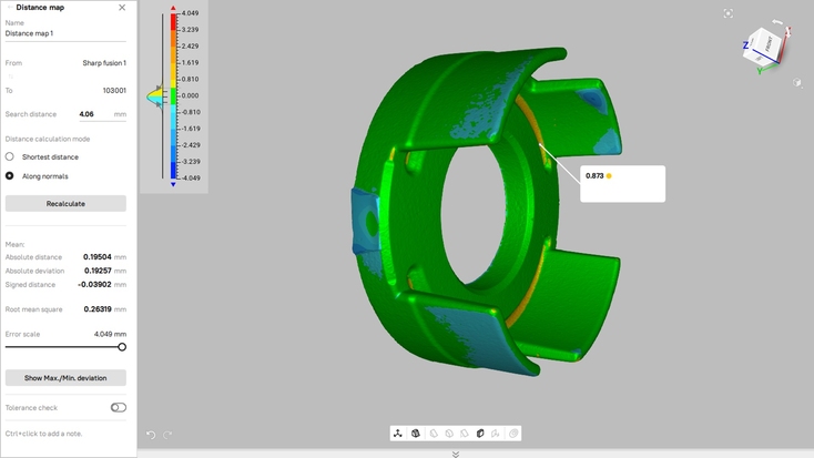
A piston casting being inspected with distance mapping in Artec Studio. Image courtesy of Ausco Products Inc.
Overall, optical CMMs have applications across the manufacturing workflow, from first-article inspection to in-process analysis, quality control, and reverse engineering for design iteration.
Aerospace
In the aerospace industry, optical CMMs are vital for ensuring precision, safety, and compliance with strict standards. This could be in manufacturing e.g. measurement during turbine engine production, fuselage assembly, or aircraft maintenance, repair, and overhaul. Yet, despite the industry’s demanding nature, accuracy requirements aren’t as high as you might think.
Sub-millimeter accuracy data capture is often sufficient for inspecting aerospace components, especially if they’re non-flight critical. Artec Gold-certified Partner 3DMakerWorld demonstrated this by reverse engineering the Sadler Vampire small aircraft with Artec Leo. In doing so, they helped a client future-proof their prized aircraft by creating a digital library of spares.
Automotive
Just like in aerospace, automotive optical CMM applications can vary wildly. One OEM might inspect welded structures prior to painting, another could use the technology to measure interior trim, and others may check powertrain or suspension parts for standard compliance.
These use cases needn’t be restricted to vehicle manufacturing either, they can easily extend into modification, whether it be the addition of spoilers, scoops, or performance-enhancing upgrades. In the US, BD Engineering has taken this principle to new extremes by creating custom Toyota Supra drifting mods, using an impressive level of tinkering and Artec Leo.
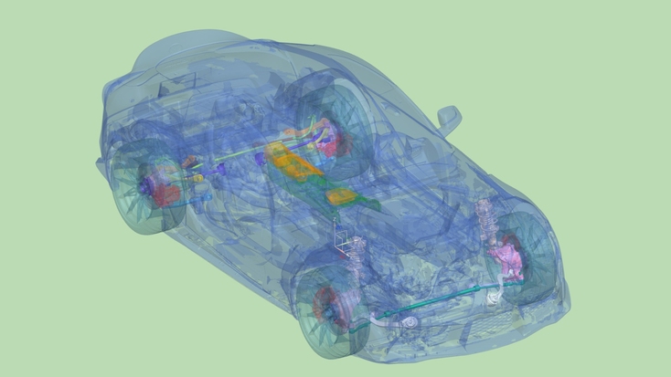
BD Engineering’s reverse-engineered Toyota Supra and planned modifications. Image courtesy of BD Engineering
Medical device manufacturing
When it comes to medical device manufacturing, optical CMMs are often used to measure knee, hip, and spinal implants for surface roughness and osseointegration. Everyday surgical instruments like scalpels, forceps, and catheters are also checked for quality control.
The shortage of high-quality medical equipment actually became a major issue during the early days of the COVID-19 pandemic. To get around this problem, 3D technologies were deployed around the globe as on-demand portable CMMs and rapid manufacturing tools. At Assistance Publique – Hôpitaux de Paris, Artec Space Spider was used for inspecting emergency medical supplies including tubing and protective masks, which kept clinicians safe in arduous times.
Key point
Optical CMMs aren’t just for inspection – they also unlock inventory digitization and customization opportunities.
Research & development
Primarily, optical CMMs are used in product R&D for verifying the dimensional accuracy of early-stage designs. It’s quick and easy to 3D scan and compare prototypes to CAD data – it’s also non-contact, making it a form of non-destructive testing. Other aspects worth considering include design validation, tolerancing, and, much earlier in the process, visualization.
In addition to product inspection, famous footwear brand ASICS uses Artec 3D scanning and photogrammetry to make highly realistic, engaging marketing materials. Running shoe models captured with incredible fidelity don’t just help the manufacturer stay on top of quality control, they help communicate the message behind its products and drive customer appeal.
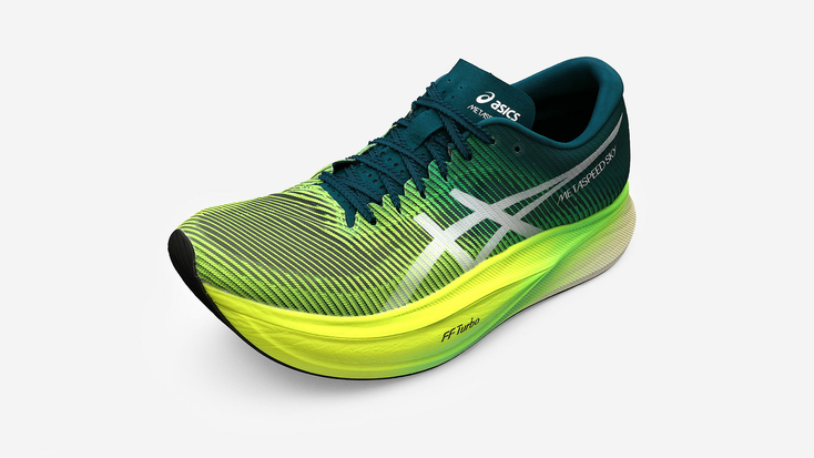
An ultra-realistic 3D model of a running shoe made with Artec 3D scanning and photogrammetry tools. Photo courtesy of the ASICS Corporation
Getting started with optical CMMs
So, what should you look for in an optical CMM? As outlined earlier, most systems operate using optical capture technology. This could be structured light, a laser, or a set of camera sensors. They’ll also require a control unit or dedicated software of some kind for data processing – and (potentially) calibration tools – such as reference targets.
When it comes to choosing the right optical CMM for your specific use case, there are a number of things to consider. Object size, for example, can play a critical role here. If your part is large, a static CMM will have neither the capacity to hold it nor the speed necessary to measure at pace. Accuracy and resolution are also important to consider from the outset.
If you’re working to sub-millimeter tolerances, you’ll need a system capable of meeting those demands. In some cases, even your workplace can play a factor (if you’re operating somewhere noisy or prone to vibrations). Lastly, geometry is a critical factor that should be at the center of your decision: certain technologies are better at capturing freeforms and holes than others!
Hopefully, that gives you an idea of what you should look for in an optical CMM. You can find out more about 3D scanning for metrology and Artec 3D scanners as metrology data capture tools via our learning center. For one-on-one advice, please contact sales@artec3d.com.
Read this next
More from
the Learning center
At times, traditional CMMs can struggle to rapidly and non-invasively measure objects, particularly when these feature holes or brittle surfaces. Fortunately, advances in 3D scanning mean it can now counter such difficulties. As such, the technology is starting to compete with CMM systems as a means of addressing various part inspection applications.
In manufacturing, it’s common to hear the phrase non-destructive testing or ‘NDT.’ But what does it actually mean? NDT is a catch-all term that describes any process of measuring or evaluating the properties of a product without having to damage it. In this article, we take a look at potential workflows, applications, and technologies for achieving the best NDT results.
Computer Aided Design (CAD) software is used by designers and engineers in different spheres in a whole range of processes. It is a mainstay in the workflows of those working in design, simulation, manufacturing, and many other areas. CAD software is useful not just for providing visual representations of design concepts or drafts, but also for documentation, without which you wouldn’t be able to do things like make patent applications and legally protect designs, or check them for compliance.


